Hydrogen Production by Water Electrolysis - Operating Data
- Chemtropia
- Jun 9, 2018
- 3 min read
Updated: Jun 29, 2020
(If some the terms and concepts used here are not familiar, then a read through the earlier notes in this series which explain the terms and the basis of the energy requirements for water electrolysis. The energy data for the system is also summarized there. )
The use of alkaline cells will not be considered further, the following is based on the use of PEM electrolysers.
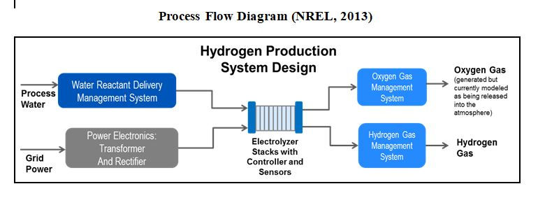
The energy usage for PEM electrolysis is based on information published by NREL in 2013 ; the basic system overview is shown below (taken from NREL).
System Operating Assumptions
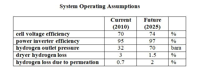
NREL give data both for ‘current’ (2010) system design and for NREL’s estimate of expected performance in 2025.
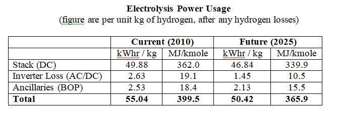
The operating assumptions and the overall power usages are shown in the tables below. These are based on the nett hydrogen flow from the electrolyzer system.
The system power requirements includes all ancillaries and the inverter power loss, and allows for loss of hydrogen due to diffusion of molecular hydrogen across the membrane and loss of hydrogen in the product dryer system. Electrolysis cells require DC electricity, the inverter converts the AC supply to a suitable DC voltage.
System Efficiency
Electrolysis efficiency is often reported in terms of the thermal energy of hydrogen produced per unit of electrical power input, usually in terms of the hydrogen NCV. The total power usage given in the second table above corresponds to a system efficiency of 61.4% (NCV basis) or 72.5% (GCV basis).
This is a ‘first law’ efficiency (as in the first law of thermodynamics) based on conservation of energy. This fails to take into account the pressure at which the hydrogen is produced and only values its thermal energy content.
Instead we can define the system efficiency as :

where :
This is the same general definition as used, for example, for a compressor or pump. As the auxiliary power loss tends to zero, then the value of the system efficiency (h) tends to the voltage efficiency (e).
A word of warning. For many systems there usually multiple ways to define ‘efficiency’ but very often sources will not define or be clear what the term is based on or what the scope of the system is, or confuse thermal energy and power. Indeed figures may not be an efficiency at all, but a specific energy usage.
Commercial electrolyzers operate at up to about 80C. In a reversible system the heat needed to close the electrolyser enthalpy balance (Qr) can be provided at the system temperature; the potential work value of this heat input is given by the Carnot cycle.
So for an isothermal process we can simply write:

where, for unit reaction:
Note that if T0 = T , then the change in exergy is equal to the change in the Gibbs Free Energy).
We can generalize the efficiency as :

There is also an exergy change associated with heating and cooling of feed and product materials to and from the system operating temperature.
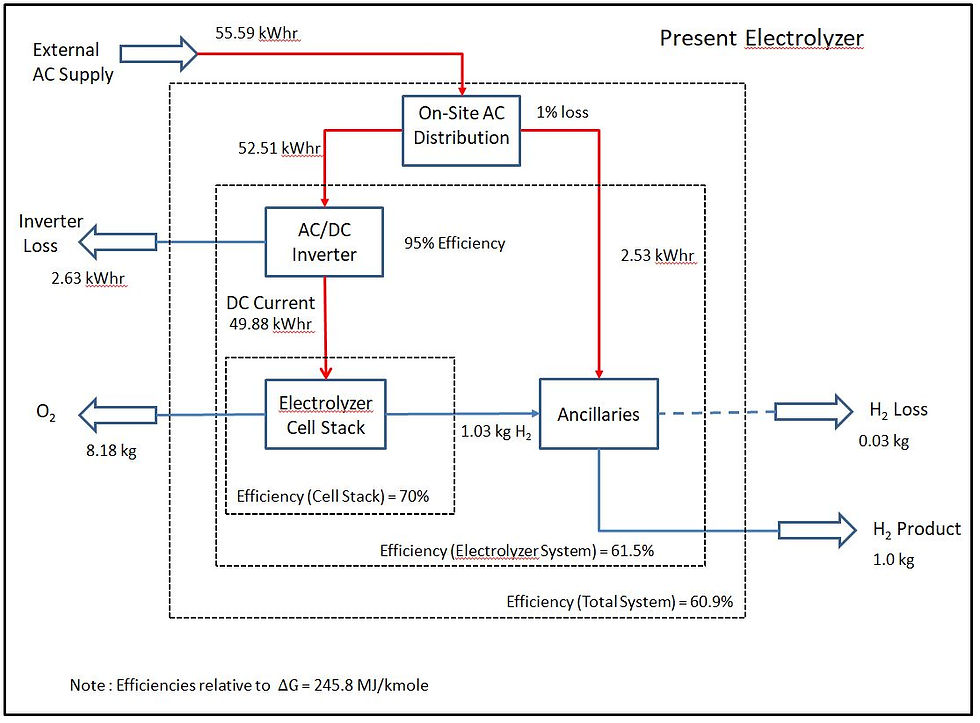
We can separate out the system into the AC/DC converter, cell stack and the ancillaries. A small portion of the hydrogen generated is lost in the hydrogen drier system within the ancillaries, as indicated in the table at the top. The hydrogen losses in the dryer occur outside of the cell stack, but we can we assume that the hydrogen lost due to permeation is oxidized within the cells.
The energy and hydrogen balances are shown below for the present and future electrolyzer operation based on 1 kg of hydrogen from the system. The quoted efficiency figures are as defined in the equation above, relative to at 25C with hydrogen at 32 bara and 70 bara respectively. The overall energy balance assumes a nominal 1% loss for distribution/transformer losses within the site.
Present (2010) Electrolyzer Operation
Future (2025) Electrolyzer Operation
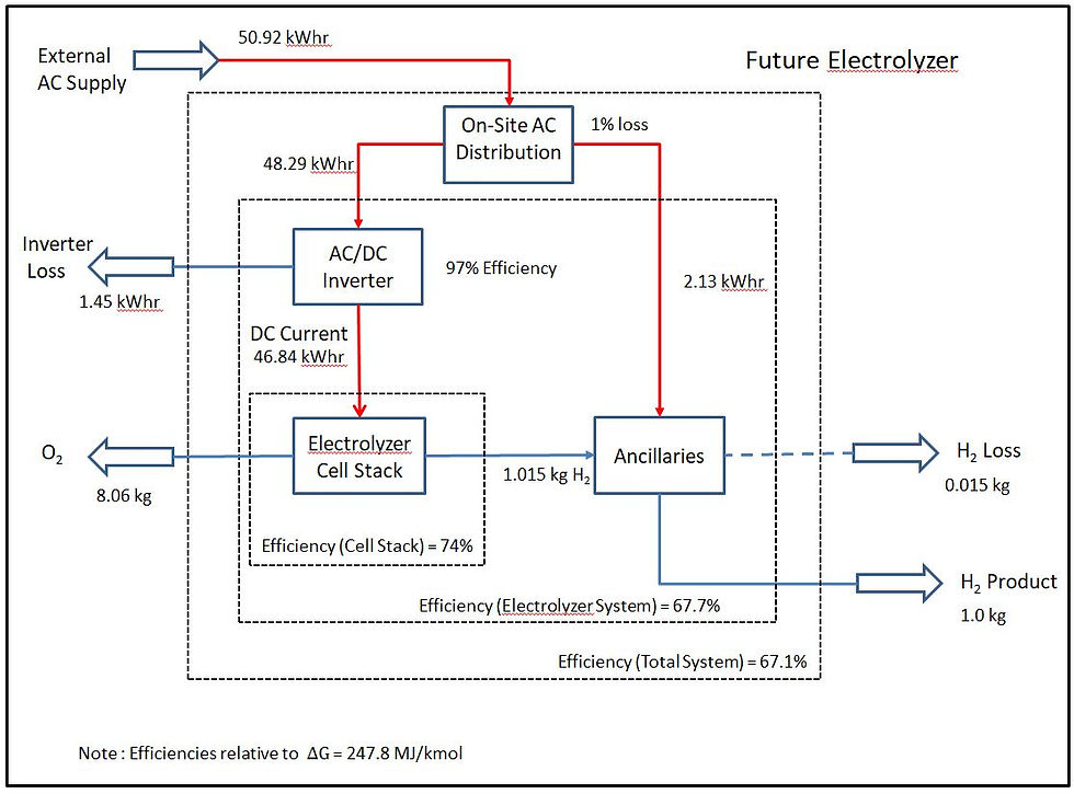
As the power input is greater than the enthalpy change the excess power input will appear as heat in the electrolysis stack. This heat will generally be rejected to the environment but nevertheless has an exergy value.
For the 2010 case the excess heat is [362 - 284.1*1.03] = 69.4 MJ/kmole.
The exergy value of this at 80C (relative to 25C) is given by the Carnot cycle efficiency as 0.156*69.4 = 10.8 MJ/kmol. In a practical ORC (Organic Rankine Cycle) the cycle efficiency at the relevant temperatures would be around 4.5% giving a power generation of 3.1 MJ/kmol (after accounting for parasitic losses). The effect on the system nett energy usage is to increase the efficiency by around 0.8%.



Comentários